
The process of removing, replacing, and reinstalling the lower assembly on the Gilson Pipetman Neo, G, & L multichannel pipettes requires great care, a high attention to detail, patience, and steady hands. Please dedicate a good work area with good lighting and space where small parts can be located should they pop out during disassembly. Pipette damage and lost parts may occur if attention to detail is not maintained. Please proceed at your own risk.
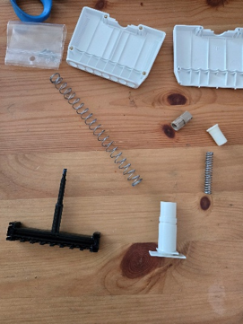
Replacement Parts:
Note: A new version of the tip holder featuring V-rings is available. Please verify whether the Pipetman Multichannel pipette in question is equipped with this updated tip holder.
Recommend Supplies:
- Gloves
- Flat-head screwdriver
- Phillip-head screwdriver
Preliminary Note(s):
The instructions cover the 10uL, 20uL, 200uL & 300uL multichannel pipettes.
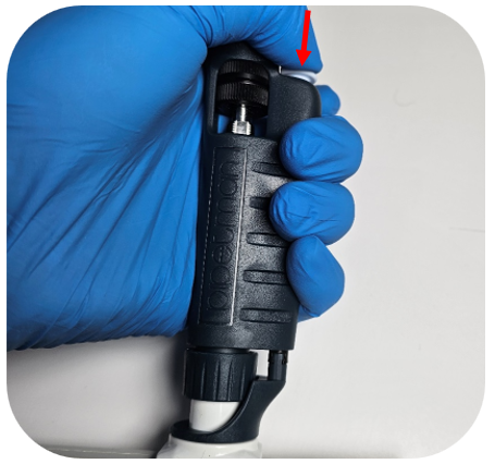
Step 1:
Press down the ejector button to expose the ejector clip.
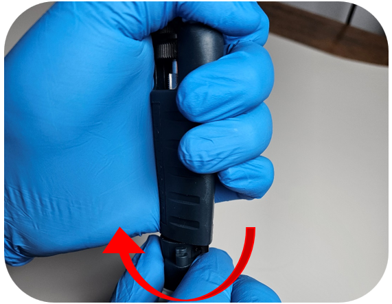
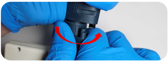
Step 2:
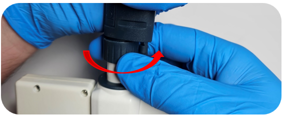
While holding the ejector button down, turn the ejector interface counterclockwise to unclip it.
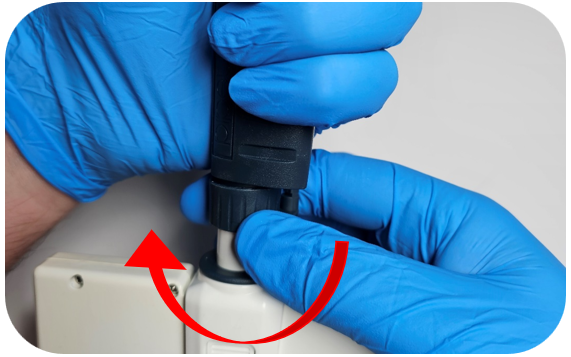
Step 3:
Turn the connecting nut counterclockwise to remove it from the pipette body.
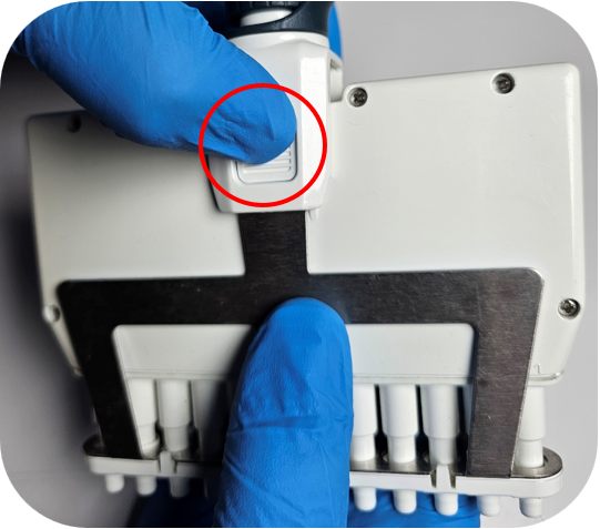
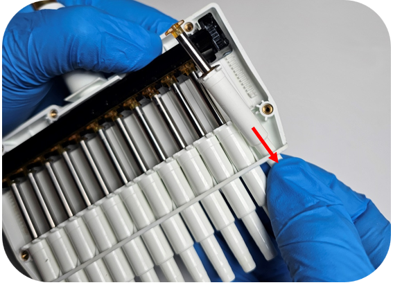
Step 4:
Remove the tip ejector by pressing the clip located on either side of the ejector interface.
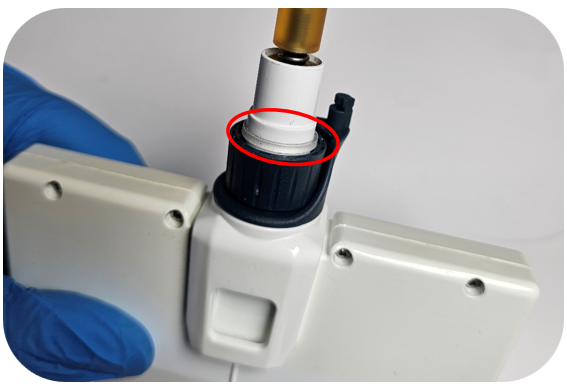
Step 5:
Ensure the connecting nut and ejector interface are in the down position. When both are down, the clear retaining clip should be visible.
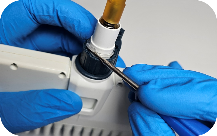
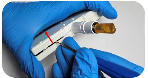
Step 6:
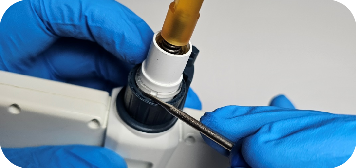
Using a small flat-head screwdriver, locate the open end of the clear retaining clip. Gently apply upward pressure on the underside of the clip to remove it.
Step 7:
Once the clip is removed, detach the connecting nut and ejector interface from the lower assembly.
Step 8:
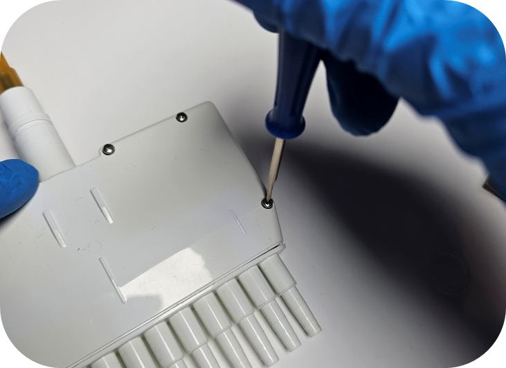
Remove all screws from the housing using a Phillips-head screwdriver.
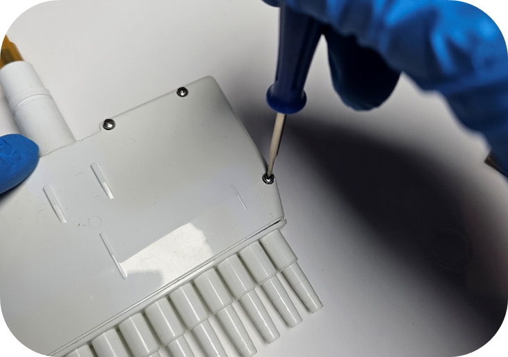
Step 9:
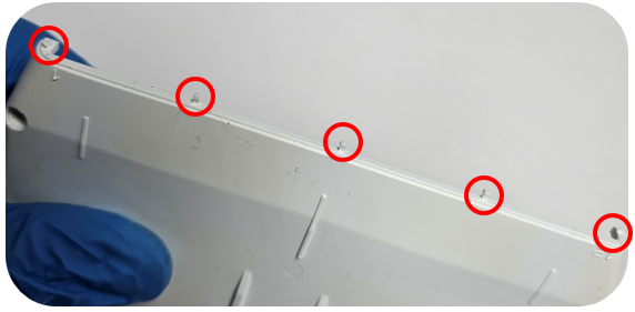
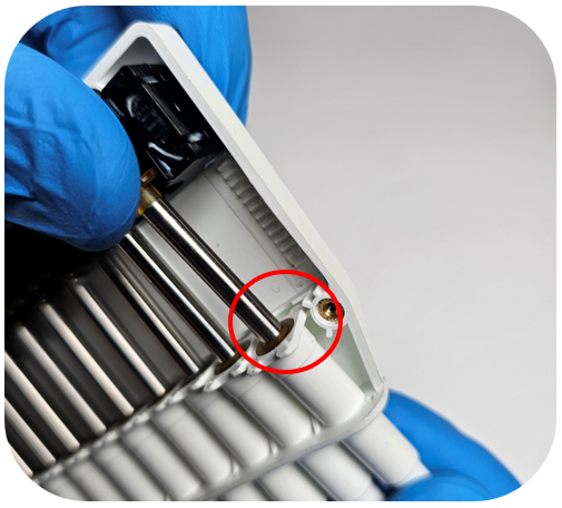
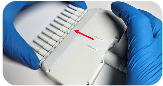
With the screws removed, carefully pry up the top section of the housing.
Note: Do not pry on the bottom end of the housing—plastic alignment tabs are located there and can be damaged. See the image below for the circled pin locations.
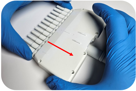
Step 10:
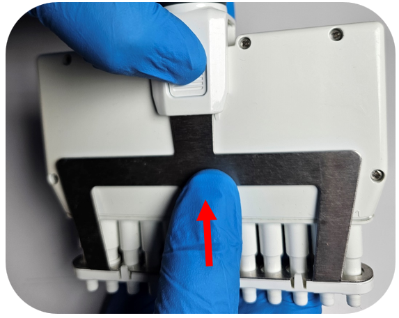
Lift up the top edge of the housing and pull it away from the bottom part of the housing to avoid damaging the plastic pins.
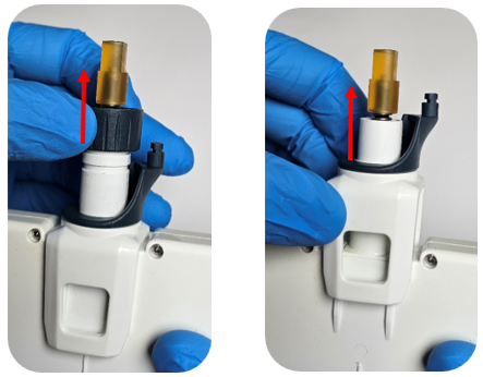
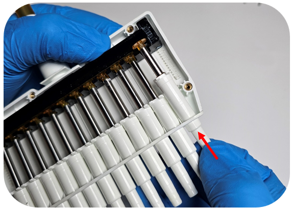
Step 11:
With the open side of the housing facing upward, press down on the tip holder to unseat the piston from the operating system.
Then push up on the tip holder to remove the piston assembly from the housing.
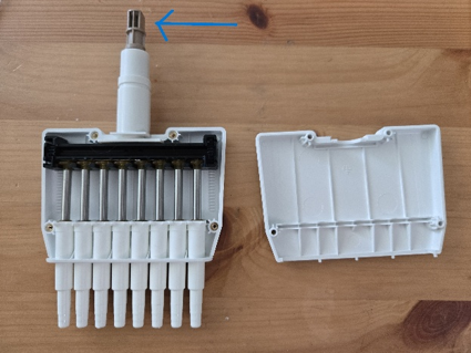
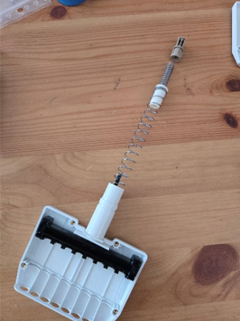
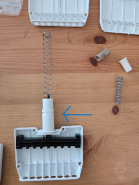
To Replace the Operating System / Manifold:
In order to replace the housing you will need to remove the plunger, which can be done by unscrewing the top brown piece. Please USE CAUTION, there are two heavily wound springs being held in place by the screws and they will fly out if you are not keeping tension on the brown piece while unscrewing. Once the brown piece is unscrewed, remove the 2 springs from the top and the black plunger from the bottom. This white piece will also need to be removed from the old housing and clipped into the new housing. Place the black plunger into the housing and put both springs through the top and push down to screw the brown piece back in. Again, USE CAUTION because these springs will pop out if you’re not holding everything down with tension.
Step 12:
To reinstall the piston, insert the tip holder into the corresponding hole in the housing. While holding the tip holder, adjust the piston so it fits into the empty slot in the operating system.
Step 13:
Hold the top of the piston lightly in the operating system and align the tip holder tabs with the front and back housing channels. Apply gentle downward pressure on the tip holder to ensure it is fully seated.
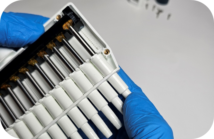
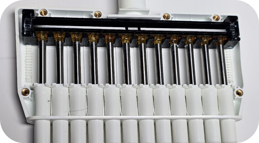
Step 14:
Before replacing the housing cover, confirm that the tops of the pistons are properly aligned (as shown below).
Step 15:
Insert the pins on the housing cover into the corresponding holes on the back half of the housing.
Step 16:
Press down on the top cover of the housing to ensure it is securely seated, then reinstall all screws using a Phillips-head screwdriver.
Step 17:
Attach the ejector interface to the top of the housing, followed by the connecting nut. Ensure all components remain in the down position.

Step 18:
Carefully press the clear retaining ring into place on the housing. You should feel a tactile “click” indicating it is fully locked.
Note: To confirm proper installation, pull gently on the connecting nut and ejector interface. If they cannot be removed, the retaining ring is correctly seated.
Step 19:
Reattach the connecting nut to the pipette body by turning the connecting nut clockwise.
Step 20:
Press down the tip ejector button and reclip the ejector interface by rotating the ejector interface towards the clip inside the pipette body.
Step 21:
Reinstall the tip ejector into the ejector interface, ensuring the ejector clips align with the grooves for a secure fit.
Related Posts:
Troubleshooting Gilson Pipetman Calibration Concerns
Gilson Pipetman L – Counter Assembly Replacement
What model of Gilson Pipette do I have?
Pipetman L Ejector Maintenance
Disclaimer: Any action you take using the information on this website is strictly at your own risk. The information herein does not constitute professional advice and is general in nature. We make no warranty that this information will meet your requirements, be safe, accurate, or error-free. Pipette Supplies, Inc. is not responsible for any errors or omissions, any results obtained from the use of this information, or any loss or damage arising out of the use of this information. This site is for educational purposes only.
Fair Use: Copyright Disclaimer under section 107 of the Copyright Act of 1976, allows for “fair use” for purposes such as comments, criticism, teaching, scholarship, news reporting, and research.
Fair use is permitted by copyright statute that might otherwise be infringing.