
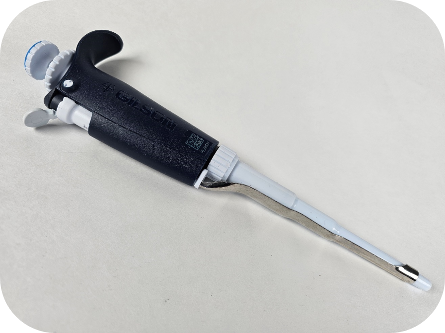
The process of removing, replacing, and reinstalling the Gilson Pipetman L counter assembly requires great care, high attention to detail, patience, and steady hands. Please dedicate a work area with good lighting and space where small parts can be located should they pop/fly out during disassembly. Pipette damage and lost parts may occur if attention to detail is not maintained. Please proceed at your own risk.
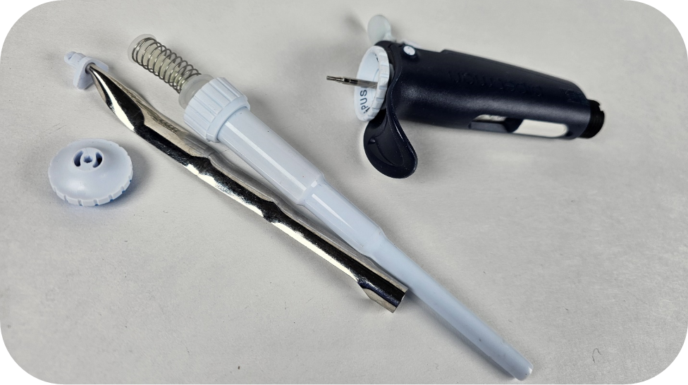
Replacement Parts:
- Cap Screws
- Counter Assemblies: Volume Specific
- Pay special attention to the description as there are autoclavable and non-autoclavable parts in the counter link above. If a non-autoclavable counter is used in an autoclavable pipette, the counter will shrink around the adjustment screw if the pipette is autoclaved. The counter will become fused making it nearly impossible to disassemble/repair the pipette.
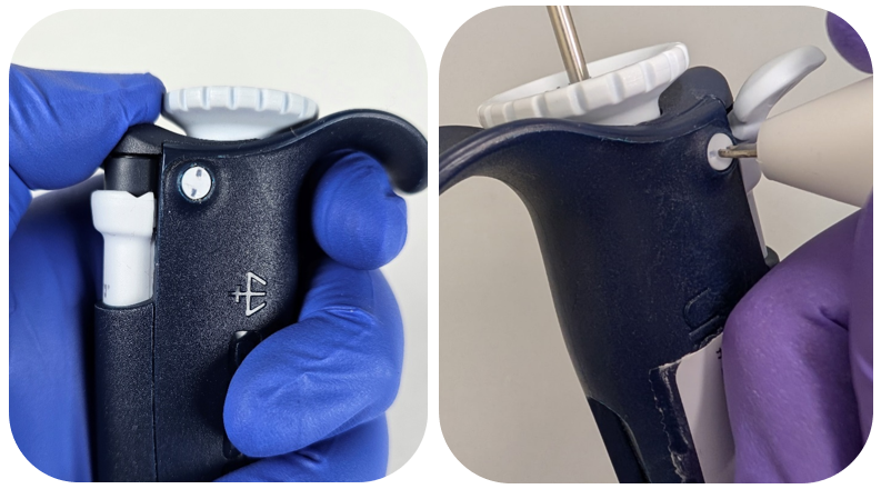
- The autoclavable models can be identified by the following symbol on the pipette body:

Recommend Supplies:
- Cap screw removal tool
- Pipetman L calibration tool
- Xacto Knife
- Needle nose pliers
Preliminary note: It is recommended to use the Pipetman L-specific tools, as they make repairs easier. We will provide instructions for completing the counter replacement without these tools. Please note that improper execution can cause marring or damage to the pipette, as all parts are made of plastic.
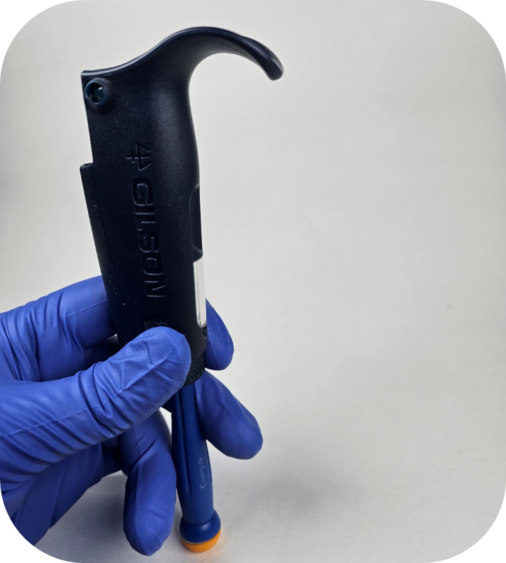
Step #1:
Start by removing the lower assembly, tip ejector, and button from the operating rod.
Note: If you do not have the Pipetman L calibration tool, it is recommended to adjust the pipette to the nominal volume prior to starting step #2.
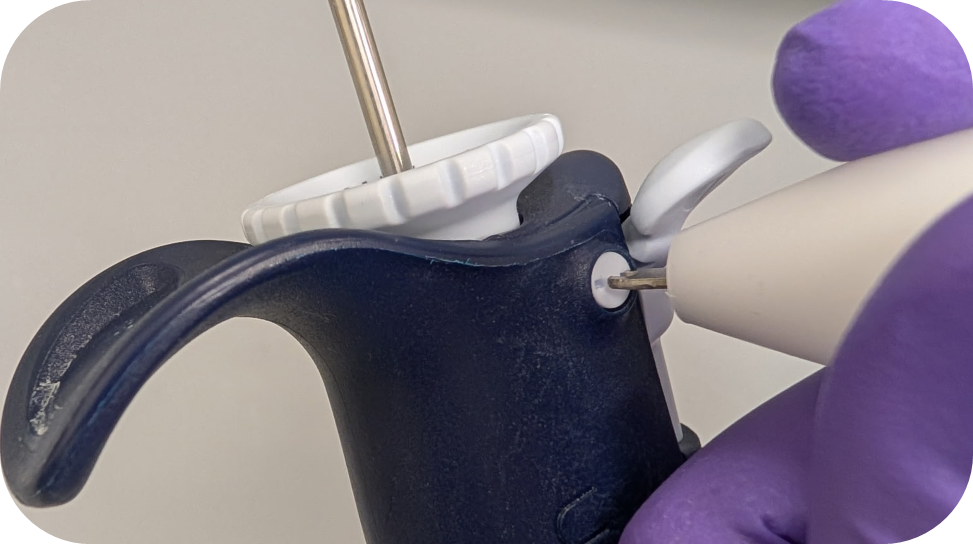
Step #2:
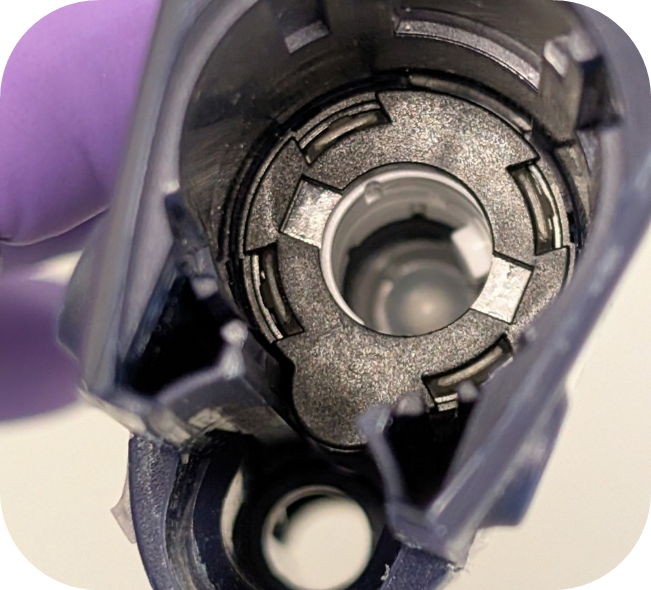
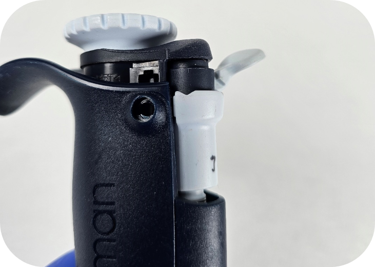
While pushing down on the blue part of the lock/unlock assembly, use the cap screw removal tool to turn the cap screw counterclockwise a quarter turn.
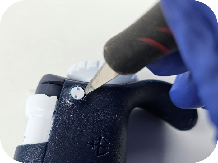
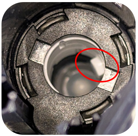
Ensure the cap screws are in the unlocked position as it is easy to turn them too far. Make sure the two indents make a vertical line as seen below:

Note: If you have trouble getting the cap screws out, an Xacto knife can be used to flick/pry the cap screw out of the hole.
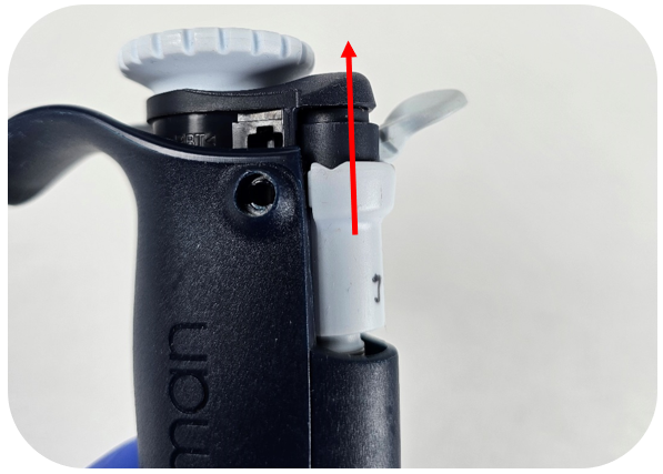
Step #3:
The lock/unlock assembly should be easily removed by pulling up on the assembly.
Step #4:
Now that the assembly is removed, invert the pipette. The bushing/collar around the adjustment screw should fall out.
Step #5:
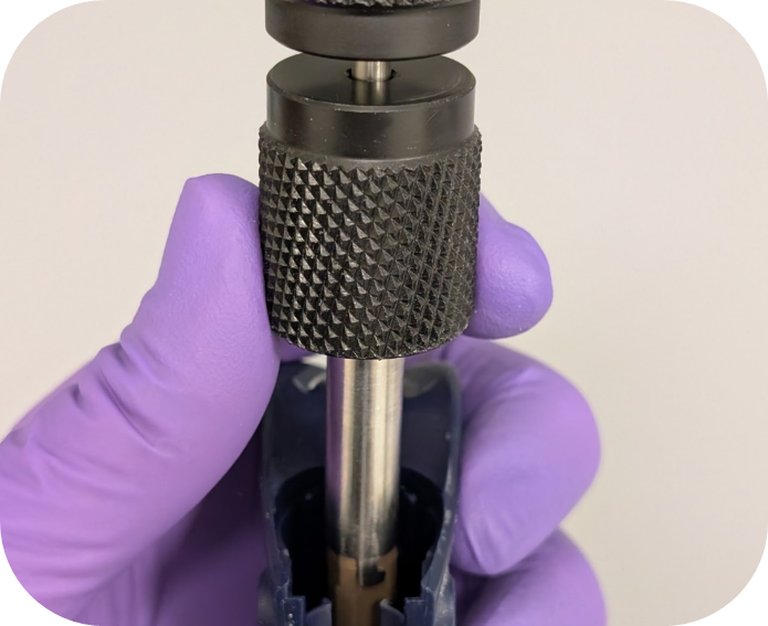
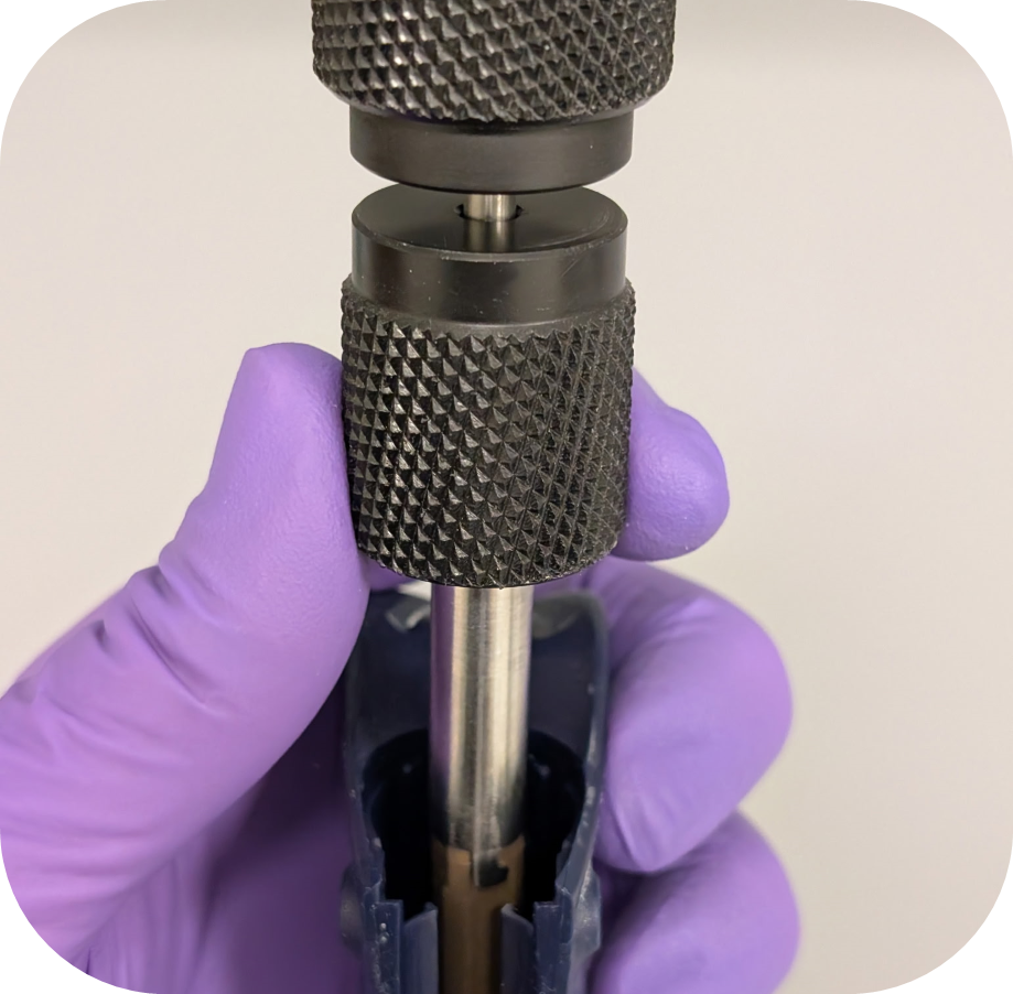
Utilizing the Pipetman L calibration tool, secure the outer teeth of the tool to the flat sides of the adjustment screw.
Note: If you do not have a calibration tool you can re-seat the lock/unlock assembly and adjust the pipette beyond the nominal volume until there is enough of the adjustment screw exposed to turn it with your fingers.
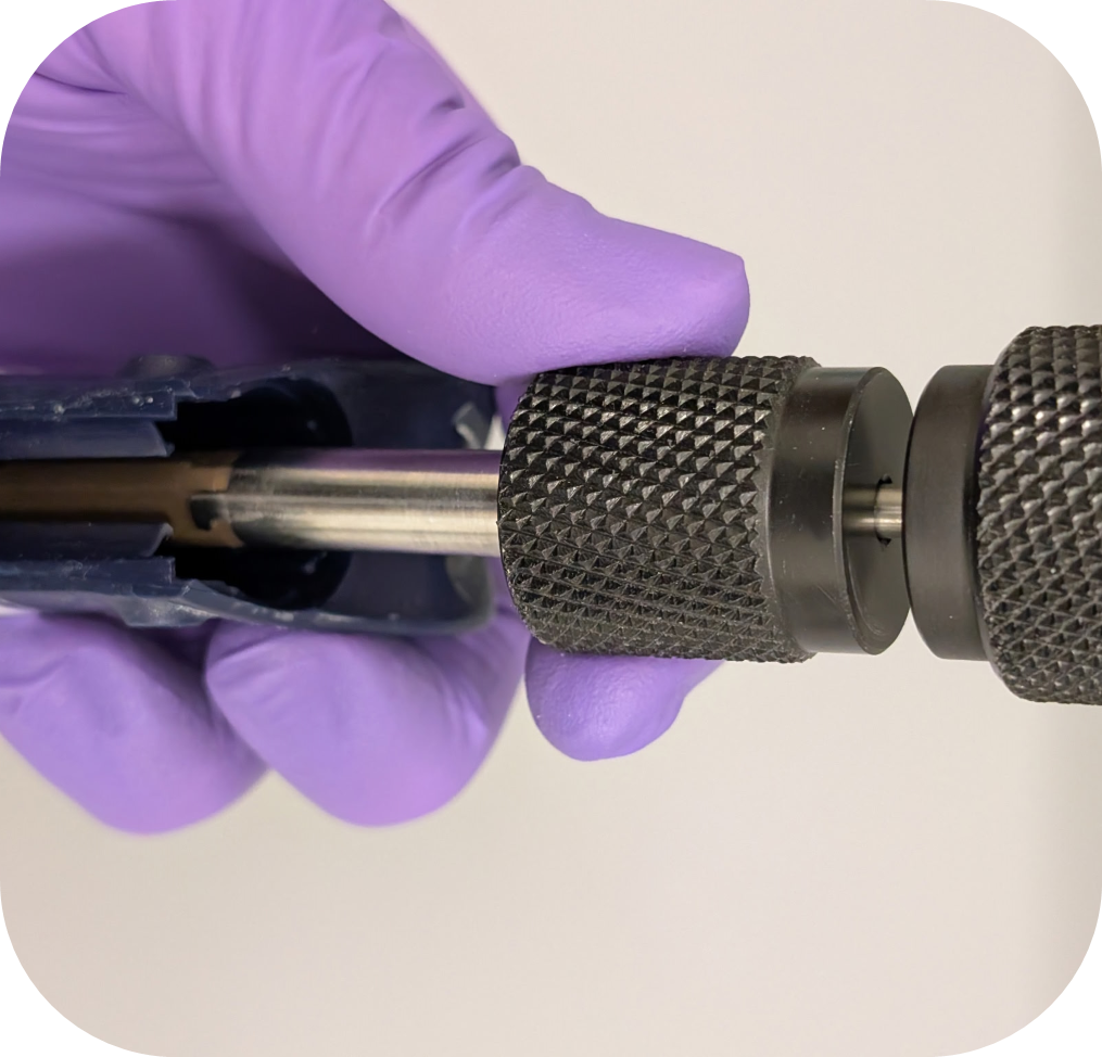
Step #6:
Turn the Pipetman L calibration tool counterclockwise to remove the adjustment screw from the pipette. Once the adjustment screw disengages, pull the calibration tool straight out to remove the adjustment screw.
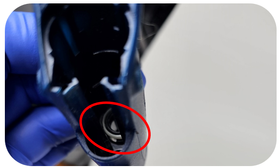
Step #7:
To remove the Pipetman L counter, insert the needle nose pliers into the adjustment screw hole in the counter and on the side containing the counter gears (circled in red below). It is important to have thin needle nose pliers to ensure you only grab the counter and not the two fins on either side of the counter gear assembly.
Note: The Gilson counter removal tool does not work for the Pipetman L and unfortunately, an updated tool is not available.
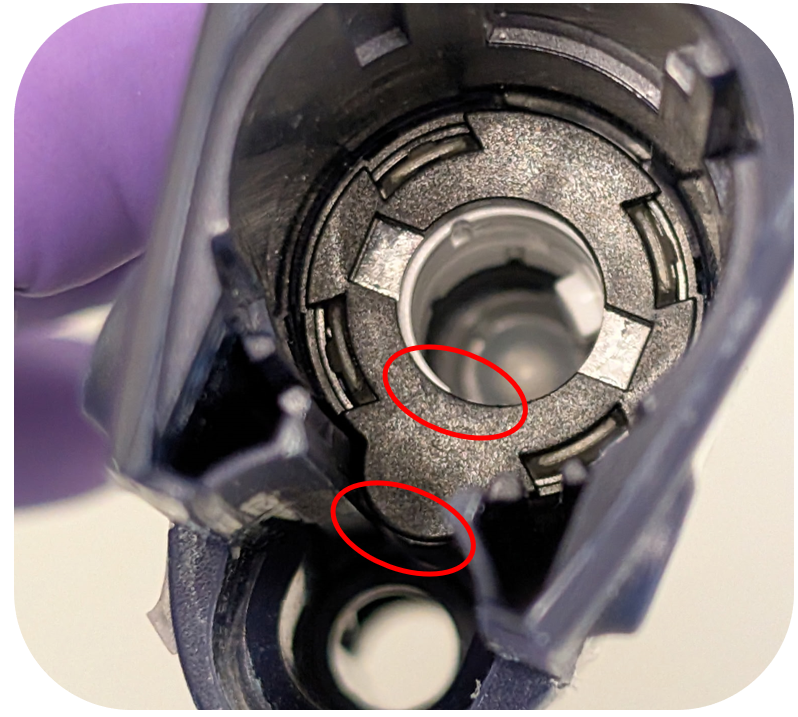
If you’re having trouble removing the counter with needle-nose pliers, you can also try using a flat-head screwdriver. After removing the adjustment screw, insert the flat-head screwdriver from the bottom of the pipette and secure it against the bottom part of the tab, pictured below. Once the screwdriver is in place, we recommend looking through the top to ensure the screwdriver is properly seated on the bottom of the counter’s tab.
While holding the screwdriver in place, gently tap or push the handle end against a flat surface. This process may take a few attempts, as the screwdriver can slip off the plastic tab. Take extra care to avoid damaging the internal threads of the pipette body when performing this variation.
Step #8:
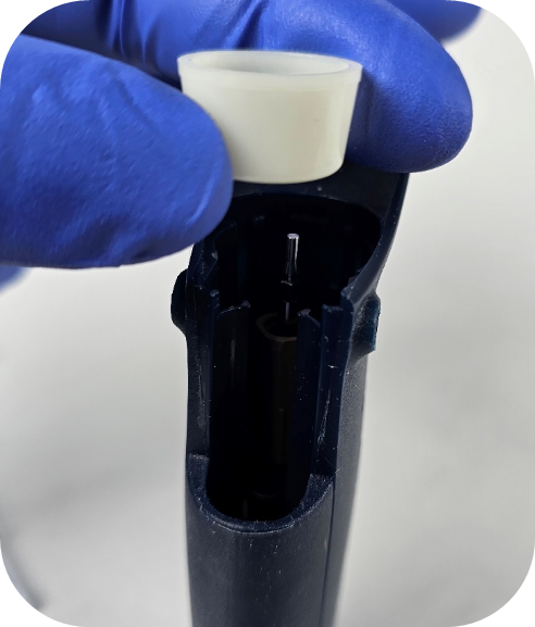
Install the new counter by applying downward pressure using your thumb or a screwdriver. A tactile click will confirm that the counter is properly seated.
Note: On the very early non-autoclavable models of the Pipetman L, the spacer (opaque white ring) below the counter was not secured in by plastic tabs. If you are working on this model, the spacer will seat once the counter is snapped into place. For the autoclavable models, the spacer stays in place and should not be removed.
Step #9:
Attach the adjustment screw to the calibration tool and line up the tooth in the counter with the channel in the adjustment screw. To ensure the correct index value is set, it is important to not engage the adjustment screw in the threads below the counter until step #10 is completed.
Step #10:
Utilize the table below to set the index value of the Pipetman L counter. It is important to ensure the adjustment screw does not engage with the thread in body below the counter when setting the index.
| Volumes | Index Value |
| 10μL, 100μL, 1000μL, 10mL | 135 |
| 2μL, 20μL, 200μL | 235 |
| 5mL | 670 |
Step #11:
Once the counter reads the value listed above, apply firm downward pressure and turn the adjustment screw/calibration tool clockwise.
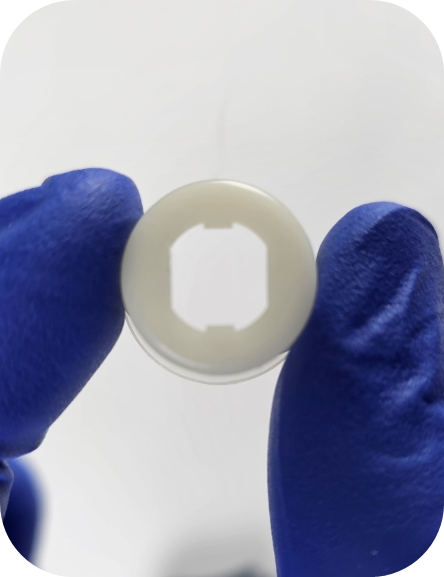
Step# 12:
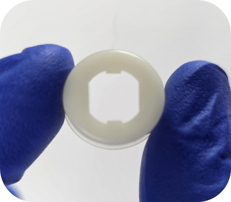
Reinstall the spacer, paying special attention to the orientation (flared side faces up) and alignment of the grooves on the adjustment screw. The spacer will slide down the adjustment screw to the counter when seated properly.
Step# 13:
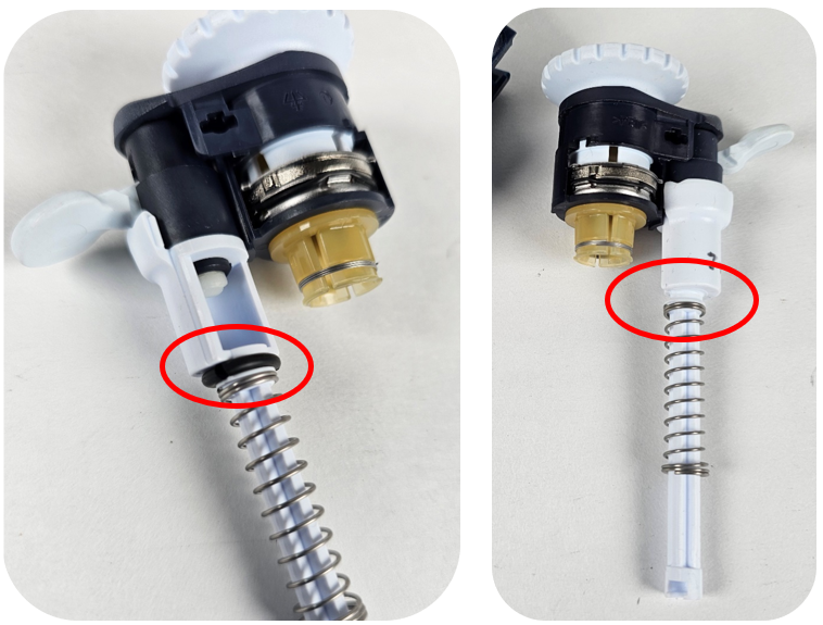
Advice from our technical experts: Before installing the lock/unlock assembly, we recommend fully removing the ejector assembly O-ring. It tends to break down and breaks into pieces. These pieces can cause the ejector button to stick and potentially lead to counter damage.
Step# 14:
Install the lock/unlock assembly utilizing slight downward pressure. Note: Ensure the lock/unlock assembly sits flush with the top of the pipette body.
Note: If the lock/unlock assembly is not flush with the top edge of the pipette body it could be caused by two things. The lock/unlock assembly is not fully seated on the adjustment screw, and/or the adjustment screw needs to be lowered further into the body of the pipette.
Step #15:
While pushing down on the lock/unlock assembly, install the new cap screws and turn them clockwise a quarter turn. It is recommended by the manufacture to use new cap screws each time the pipette body is opened. It is possible to reuse cap screws, but it can be difficult to remove the cap screws multiple times.
Step #16:
Reattach the tip holder assembly, tip ejector, and button that was removed in step #1.
Step #17:
It is important to calibrate and verify the pipette is operating within manufacturer or customer-specific specifications before returning the pipette to service.
Related Posts:
Counter Assembly Instructions for Gilson Pipetman / Rainin Classic
Pipetman L Ejector Maintenance
Gilson Pipetman L Calibration Tool, Item # 28888
Gilson Pipetman Teflon vs. Polyethylene Seals
Disclaimer: Any action you take using the information on this website is strictly at your own risk. The information herein does not constitute professional advice and is general in nature. We make no warranty that this information will meet your requirements, be safe, accurate, or error-free. Pipette Supplies, Inc. is not responsible for any errors or omissions, any results obtained from the use of this information, or any loss or damage arising out of the use of this information. This site is for educational purposes only.
Fair Use: Copyright Disclaimer under section 107 of the Copyright Act of 1976, allows for “fair use” for purposes such as comments, criticism, teaching, scholarship, news reporting, and research.
Fair use is permitted by copyright statute that might otherwise be infringing.