How to Remove and Install a New Counter Assembly for Gilson Pipetman with the Counter Disassembly/Assembly Tool
In this post:
Counter Removal Tool: PS 10002
Gilson Counter Assemblies
Pipetman Classic Replacement Parts: Single Channel
NOTE: These instructions are not recommended for the Pipetman L. You can find Pipetman L Counter Assembly instructions here.
Disassembly
Step 1:
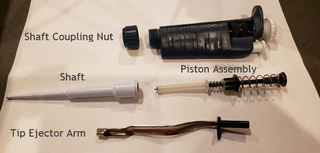
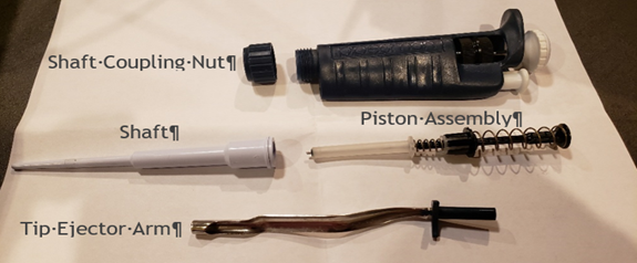
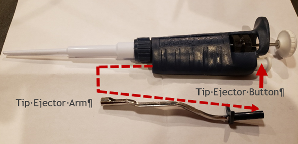
Press and hold down the white colored tip ejector button. This will slightly lower the stainless-steel tip ejector arm and make it easier to remove. With a little force, carefully pull down on the tip ejector arm to detach and remove it from the pipette body. Lay aside for reassembly later.

Step 2:
Carefully unscrew the shaft coupling nut from the pipette body.
CAUTION: When the shaft coupling nut is removed from the pipette body, the internal piston assembly might forcefully pop out from inside the white colored shaft. Take great care so the internal piston assembly and components do not pop and fly out of the shaft, or you may be forced to locate and or replace the seal, O-ring, seal retainer, stroke spring, blowout spring, or piston, if lost. Internal piston assembly components may vary slightly based on pipette nominal volume size. Lay aside for later.
Step 3:
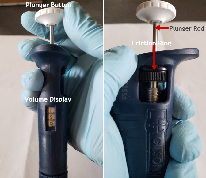
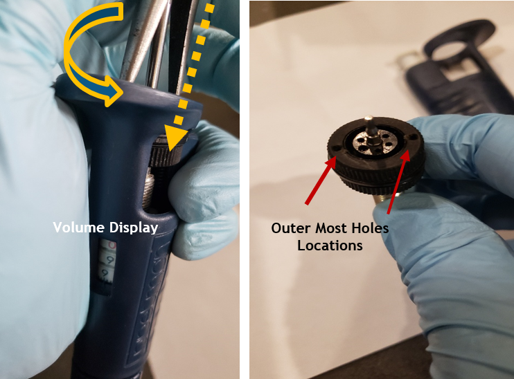
Turn the to adjust the pipette plunger button and volume display to nominal volume (i.e., 100% of the pipette volume)
Step 3A:
Then gently rotate the volume increasingly past nominal volume until the plunger button and volume display will not rotate further. STOP and do not force the volume turning further. Usually this occurs when the friction ring contacts the top portion of the pipette body.
Step 3B:
Remove the plunger button from the pipette by pulling upward and away from the plunger rod. Lay aside for later.
Step 4:
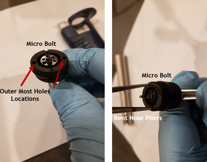
Insert bent nose pliers into the two outer most holes on the black colored micro bolt and continue to rotate the micro bolt in an increasing manner until it can be removed and pulled out from the pipette body. Lay aside for reassembly later.
NOTE: the bent nose pliers will provide the extra torque needed to allow the micro bolt and friction ring to be removed from the pipette body.
COMMENT: If desired, you may cut off the plastic or rubber friction ring from the micro bolt with a razor blade prior to Step 3A. This means you will need to replace the friction ring with a new one, prior to reassembly. If the friction ring is not cracked or brittle, replacement is usually not needed.
Photo Comments (below): The micro bolt was already removed from the pipette body to show the outer most holes easier for viewing purposes.
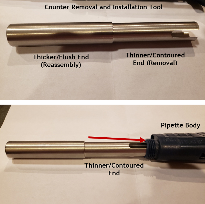
Counter Removal Tool Illustration (PS 10002): Shown to identify each end for intended use during removal and installation
Step 5:
Insert the slightly thinner and contoured end of the counter removal tool into the pipette body opening.
CAUTION: if the counter removal tool does not insert easily into the body opening and feels like it is being forced into the body, stop! Please do not force the tool into the body or it may get stuck, damage the pipette body, and require excessive force to remove the tool. Based on the age of the pipette, there is a possibility that the body opening may have shrunk slightly due to properties of the materials, environmental, age of the instrument, etc.
Step 6:
With the thinner contoured end fully inserted into the pipette body opening, gently tap or bang the end of the counter removal tool vertically onto a hard surface such as a table or bench top 2-3 times to unseat the counter assembly from the pipette body. This should be done vertically as shown.
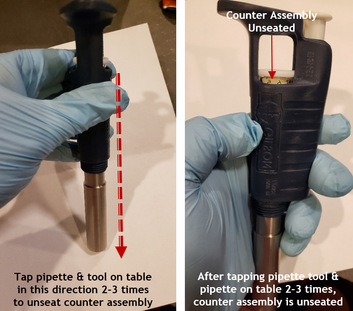
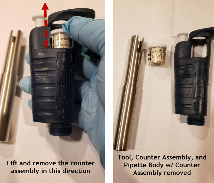
Step 7:
Remove the counter assembly tool from the pipette body and lay aside. Then, lift and remove the counter assembly out of the top of the pipette body.
New Counter Assembly, Installation, and Pipette Reassembly
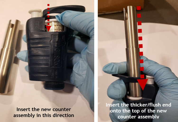
Step 8 REASSEMBLY:
Carefully align and gently insert the new counter assembly into the top of the pipette body.
Step 8A:
Insert the thicker/flush end of the counter assembly tool on top of the new counter assembly and gently push the new counter assembly until it is seated properly and fully into the pipette body. Once the counter assembly is properly seated, remove the counter assembly tool.
Step 9:
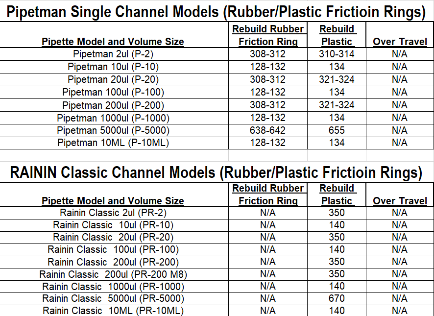
Refer to Appendix 1 and obtain the proper counter assembly digits needed for insertion of the micro bolt assembly back into the pipette body based on the nominal size of the pipette (i.e., 200uL, 1000uL, etc.). Loosely insert the micro bolt into the counter assembly and gently rotate until the desired counter assembly digits appear in the volume display window.
IMPORTANT: DO NOT ALLOW the micro bolt to seat into the pipette body until the desired digits are visible in the volume display window. This can be achieved by rotating the micro bolt and lifting it back out of the pipette and re-inserting it until the desired volume digits are visible in the volume display window.
Example: If the desired digits are 134 for a 1000uL pipette, loosely insert the micro bolt, rotate the micro bolt without it catching in the body, and remove/repeat until the micro bolt displays 134 in the volume display window.
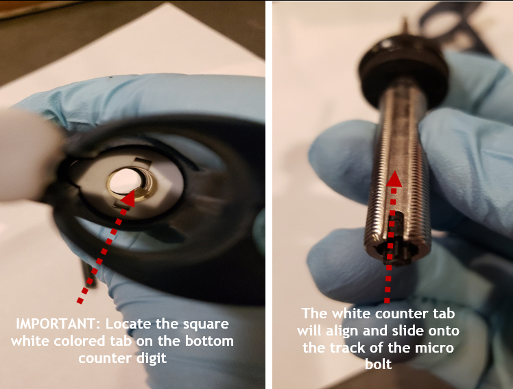
Step 10:
Align the micro bolt assembly with the white colored notched tab on the counter assembly. Once aligned, insert and push the micro bolt into the body fully until it stops/seated.
Step 11:
Insert the bent nosed pliers into the two outer most holes on the micro-bolt.
Step 11A:
After insertion, press down and maintain force while turning the bent nosed pliers to seat the counter assembly fully back into the pipette body. Provide sufficient torque to allow the friction ring to seat back in place.
Step 11B:
When rotating the bent nosed pliers, the volume display digits will decrease as the micro bolt is seated back into place. Continue until the friction ring is below the top portion of the pipette body and the micro bolt can be rotated by hand and no longer with the pliers.
Step 11C:
Wind the pipette to the 10% volume.
Step 12:
Insert the piston assembly back into the shaft and place the coupling nut back on the shaft. Fully screw the shaft coupling nut back onto the pipette body.
Step 13:
Press down on the tip ejector button and reattach the tip ejector arm to the pipette body.
Step 14:
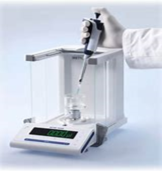
Verify the desired accuracy and precision of the pipette is obtained on an appropriate balance. Calibration adjustments may be needed.
Appendix 1: Counter Assembly Alignment Digit Settings
Disclaimer: Any action you take using the information on this website is strictly at your own risk. The information herein does not constitute professional advice and is general in nature. We make no warranty that this information will meet your requirements, be safe, accurate, or error-free. Pipette Supplies, Inc. is not responsible for any errors or omissions, any results obtained from the use of this information, or any loss or damage arising out of the use of this information. This site is for educational purposes only.
Fair Use: Copyright Disclaimer under section 107 of the Copyright Act of 1976, allows for “fair use” for purposes such as comments, criticism, teaching, scholarship, news reporting, and research.
Fair use is permitted by copyright statute that might otherwise be infringing.

Hello! Do you have instructions on how to unseat the counter assembly in the Pipetman L after removing the white cap screws and the lock/unlock assembly?
Hi Sam,
Happy to help! We will reach out via email to assist.
Hello!
I have the same question ❓.
Do you have instructions on how to unseat the counter assembly in the Pipetman L after removing the white cap screws and the lock/unlock assembly?
Hi Farid,
Sure thing! We will be reaching out via email shortly.
Good afternoon. I am working on a micropipette project. Can I get to know about the counter assembly and how it is used in chnaging the volume for aspiring the liquid. What actual mechanism is used. Can you provide me in details information about this.
Pranit Magdum
+91 97673 27692
Hi Pranit,
Thank you for your comment. We will be reaching out soon via email to get more information!
I would also know about unseating the counter assembly in the Pipetman L.
Sure thing! We will reach out shortly.
Thanks so much for your excellent how-to-guides. I have a pipetman L and would like to know how to remove the plunger rod after removing the white cap screws and the lock/unlock assembly. I purchased the Gilson pipetman counter removal from you last week – which works great! Just need additional info for the pipetman L’s.
Hi Danielle,
Absolutely! We will be reaching out via email shortly.
Hey,
I am trying to fix some misaligned counters in our lab, since we have the Pipetman L, I would have the same question:
How to unseat the counter assembly in the Pipetman L?
Thanks for the tutorial so far!
Hi Patrick,
I’ve followed out via email with more information. Thanks!