
The process of removing, replacing, and reinstalling the Pipetman Push Rod Ejector Assembly requires great care, a high attention to detail, patience, and steady hands. Please dedicate a good work area with good lighting and space where small parts can be located should they pop/fly out during disassembly. Pipette damage and lost parts may occur if attention to detail is not maintained. Please proceed at your own risk.
These instructions are ONLY applicable for Gilson Pipetman Single Channel and Multichannel Pipettes that use this ejector rod system: GI F144872. This includes Pipetman pipettes with tip ejectors that have the blue plastic piece.
Recommended Service Tools
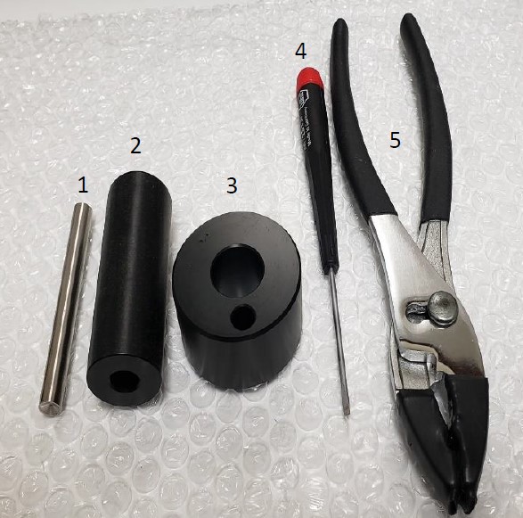
The following tools pictured here are strongly recommended to properly service, repair, or replace the Gilson Pipetman push rod ejector assembly.
- Clip Removal Tool (Locking Ring Tool): PS 10003
- Ejector Rod Tool (Calibration Tube): PS 10004
- Pipette Body Platen: PS 10001
- Flat Head Screwdriver: Source Locally
- Pliers w/ Rubber Nubs: Source Locally
Disassembly Instructions
Step 1:
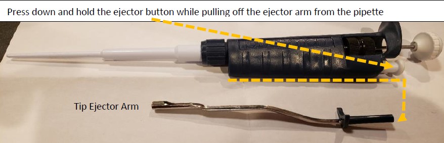
Remove the tip ejector arm from the pipette by pressing and holding down the white colored ejector button. With the button held down, pull off the tip ejector arm and lay aside for reassembly.
Step 2:
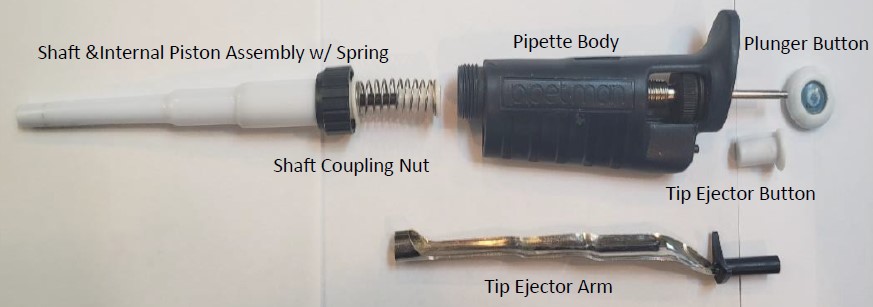
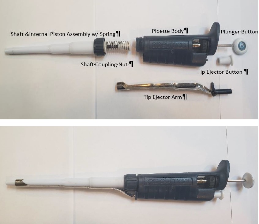
Unscrew the shaft coupling nut. Remove the shaft and internal piston assembly.
CAUTION: Be careful when unscrewing the coupling nut. The piston spring is under tension and may fly out with the piston assembly parts. Lay the piston assembly, shaft, and shaft coupling nut next to the tip ejector arm for reassembly later.
Step 2A:
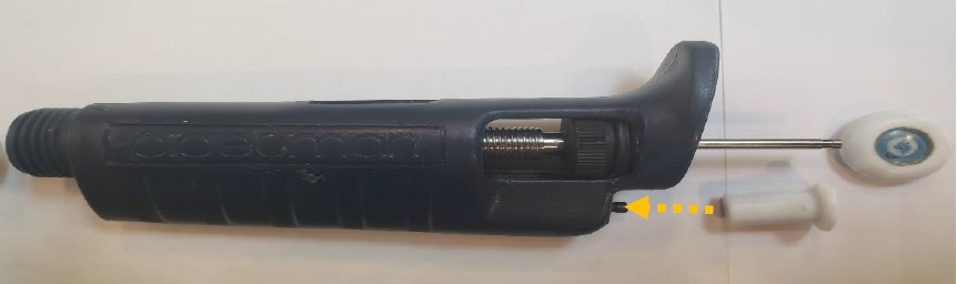
Pull off the plunger button and use the pliers with rubber nibs to remove the ejector button.
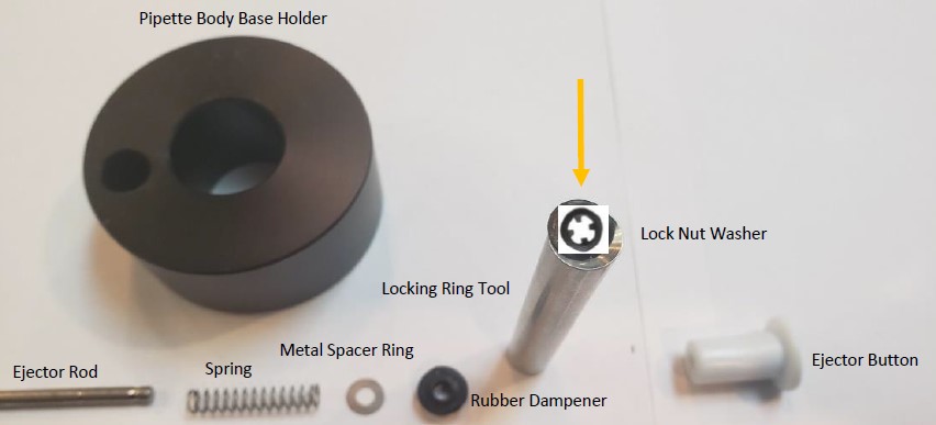
Step 3:
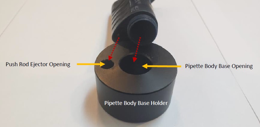
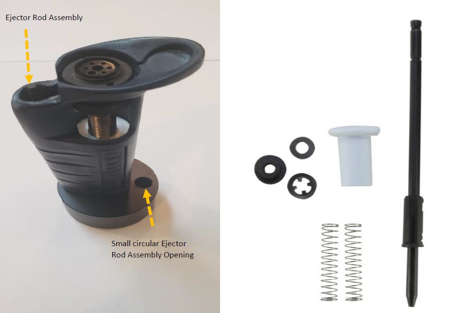
Notice the two circular openings of the platen holder, pictured below. The large circular opening is used to hold the pipette vertically in the holder The small circular opening is for the push rod ejector. Stand the pipette body in the platen holder.
Step 4:
With a small-bladed flat head screwdriver, pry off the lock nut washer from the push rod ejector assembly. It may become damaged and will need to be replaced. Slide and remove all the ejector rod components from the bottom of the pipette body, as shown below.
NOTE: Based on the era of your Pipetman, some components may look slightly different.
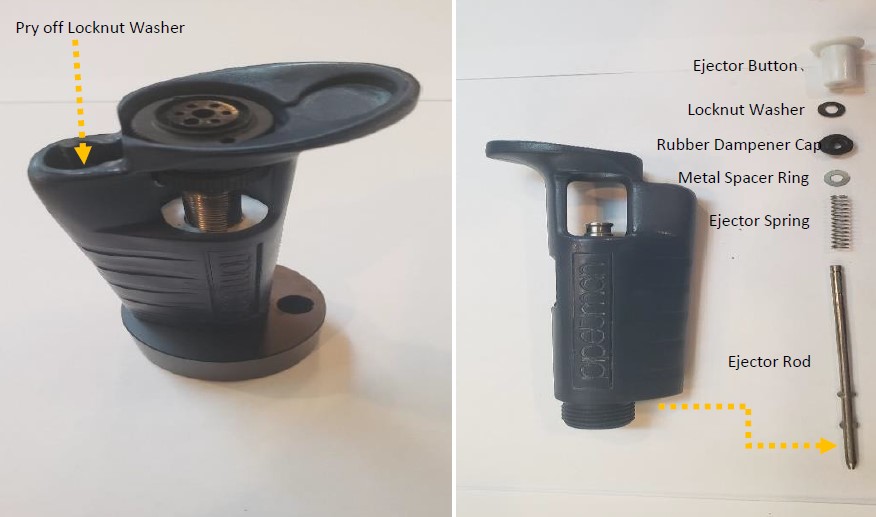
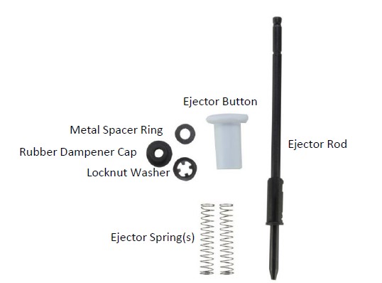
Step 5:
Based on the era of your Pipetman, the replacement push rod ejector assembly part number is likely GI F144872 and contains the parts as shown in the picture below.
Step 6:
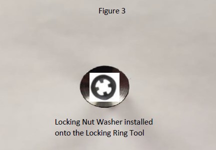
Place the replacement locknut washer onto the clip removal (locking ring) tool.
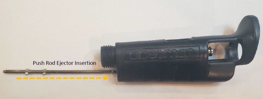
Step 7:
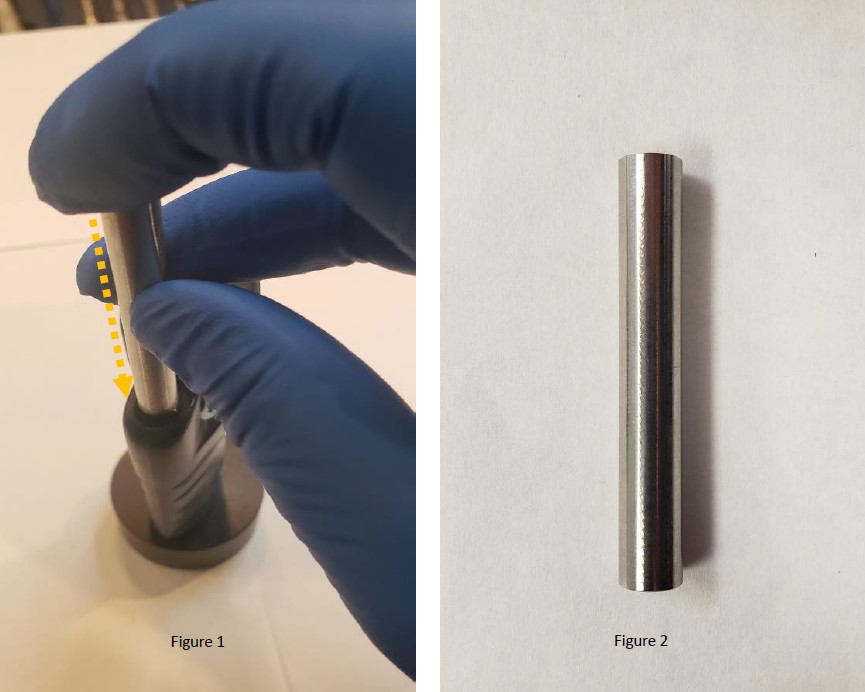
Fully Insert and hold the metal ejector rod assembly back into the pipette body through the bottom opening.
Step 8:
With the ejector rod inserted and held inside the body, place the pipette body onto the base holder as shown in the picture to the right. If done correctly, you will see the top of the ejector rod assembly sticking slightly out of the top of the pipette.
NOTE: Keep the small circular hole opening on the right side of the base and away from the ejector rod assembly for this process.
Step 9:
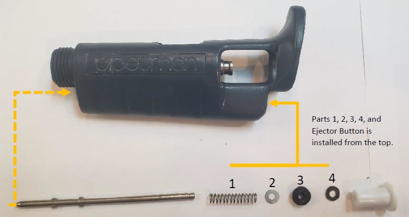
Install the replacement push rod ejector components onto the top portion of the push rod assembly in the order as shown in the picture below.
NOTE: #4 locknut washer will be installed onto the clip removal (locking ring) tool for installation.
Step 10:
With the ejector rod inserted through the bottom of the pipette, and the spring, metal spacer ring, and rubber dampener inserted through the top of the pipette, place the locknut washer onto the locking ring tool. Figure 3.
Step 11:
As shown in figure 1, insert the clip removal (locking ring) tool face down into the push rod ejector rod, push the tool down to seat, and lock the locking ring onto the push rod ejector rod. If needed, tap the end of the
locking ring tool with a rubber mallet to seat the locking ring into place. Remove the tool.
Step 12:
Install the tip ejector button back onto the ejector rod. Tap with a rubber mallet if needed.
Step 13:
Install the shaft and internal piston assembly back into the pipette body. Reattach the tip ejector arm to the pipette body. Test and recheck work if needed.
Related Posts:
Counter Assembly Instructions for Gilson Pipetman / Rainin Classic
Gilson Pipette Legend
Styles of Gilson Pipette Tip Ejectors
Troubleshooting Gilson Pipetman Calibration Concerns
Gilson Pipetman Counter Assembly Realignment
Disclaimer: Any action you take using the information on this website is strictly at your own risk. The information herein does not constitute professional advice and is general in nature. We make no warranty that this information will meet your requirements, be safe, accurate, or error-free. Pipette Supplies, Inc. is not responsible for any errors or omissions, any results obtained from the use of this information, or any loss or damage arising out of the use of this information. This site is for educational purposes only.
Fair Use: Copyright Disclaimer under section 107 of the Copyright Act of 1976, allows for “fair use” for purposes such as comments, criticism, teaching, scholarship, news reporting, and research.
Fair use is permitted by copyright statute that might otherwise be infringing.