
The process of removing, replacing, and reinstalling the Rainin Pipet-Lite/Pipet-Lite XLS/PIpet-Lite XLS+ Counter Assembly requires great care, a high attention to detail, patience, and steady hands. Please dedicate a good work area with good lighting and space where small parts can be located should they pop/fly out during disassembly. Pipette damage and lost parts may occur if attention to detail is not maintained. Please proceed at your own risk.
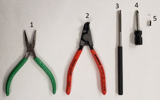
Recommended Service Tools
The following tools are strongly recommended to properly service, repair, or replace the Rainin push rod ejector assembly and/or the internal volume assembly.
- Needle Nose Pliers
- Bent Nosed Pliers: PS 10007
- C-Clip Insertion Tool: PS 10005N
- C-Clip Removal Tool: PS 10006N
- Replacement C-Clips: PS 1555C
Pipet-Lite/Pipet-Lite XLS/Pipet-Lite XLS+ Counter Assembly Replacement
**NOTE: Pipette Supplies does not currently sell the Pipet-Lite counter assemblies or body retainer assemblies.**
Step 1:
Complete Rainin Push Rod Ejector Assembly Replacement through Step 8.
Step 2:
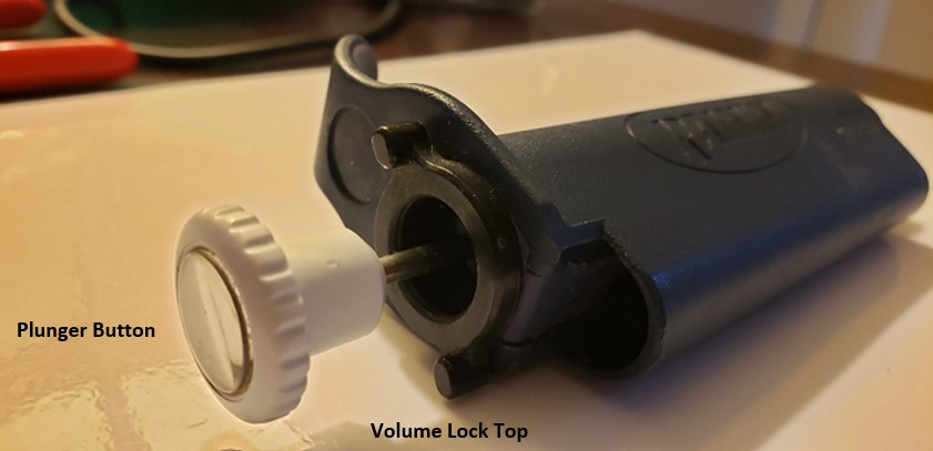
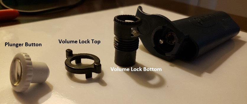
Remove the plunger button, volume lock top, and volume lock bottom from the pipette handle. The plunger button and volume lock top can be pulled directly off the pipette.
Step 3:
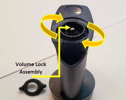
Unscrew the volume lock bottom and remove it from the pipette body.
Step 4:
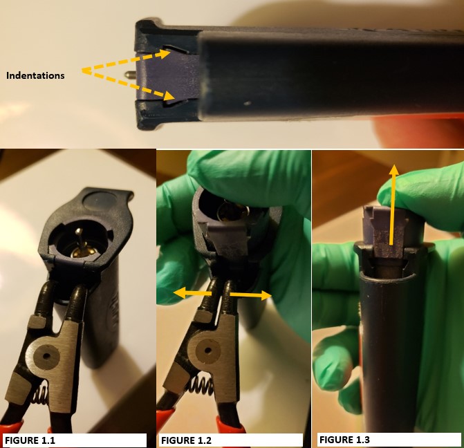
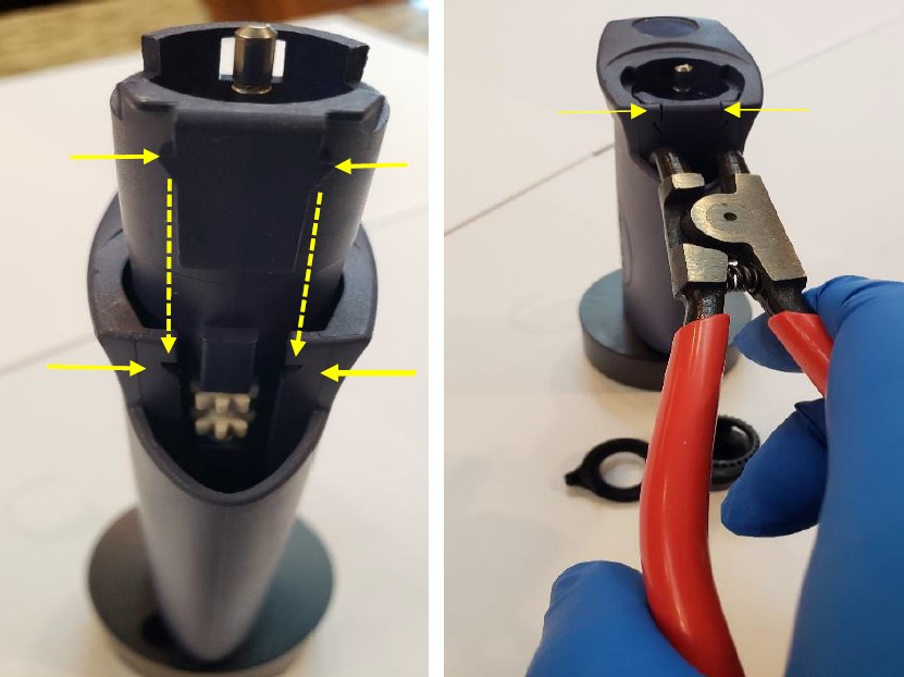
Notice the indentations on the internal volume assembly. These indentations will be spread apart with the bent-nosed pliers to remove the internal volume assembly from the pipette body.
CAUTION: Place your thumb on top of the volume assembly prior to step 5. DO NOT remove your thumb or internal contents will fly out when step 5 is performed.
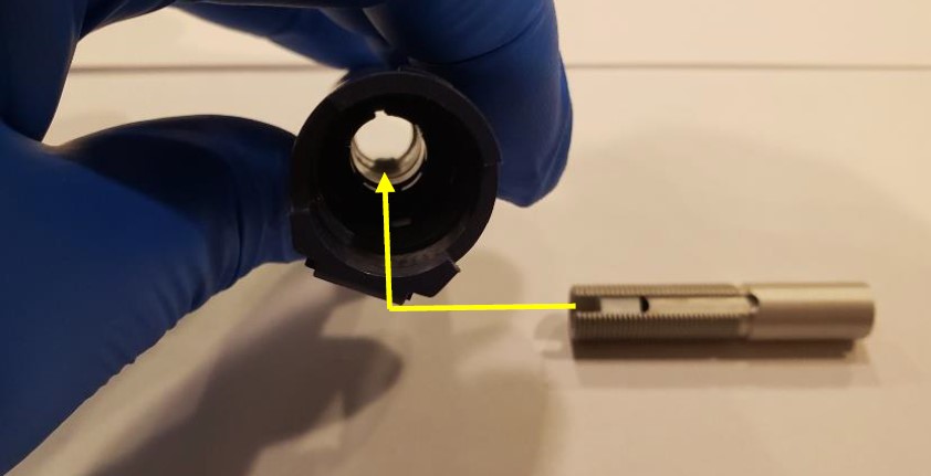
Step 5:
Insert the bent-nosed pliers into the opening that is vacated by the tip ejector button (Figure 1.1). Gently squeeze the handle of the bent-nosed pliers to have the internal volume assembly pop out of the pipette (Figure 1.2).
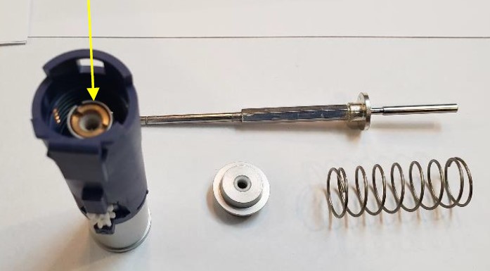
Step 6:
Remove the bent-nosed pliers from the pipette body. Internal volume assembly is now accessible as in figure 1.3
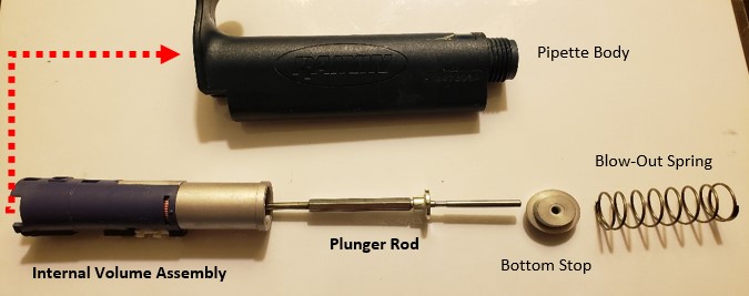
Step 7:
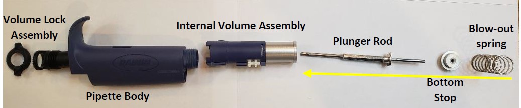
With the internal volume assembly removed from the pipette, remove the:
- Blow-out spring from the pipette body
- Bottom stop
- Plunger rod
Step 8:
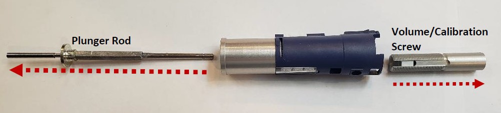
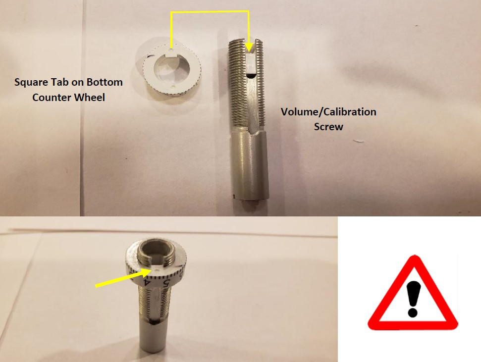
Notice the volume/calibration screw seated in the volume assembly. This will be removed next with the plunger rod.
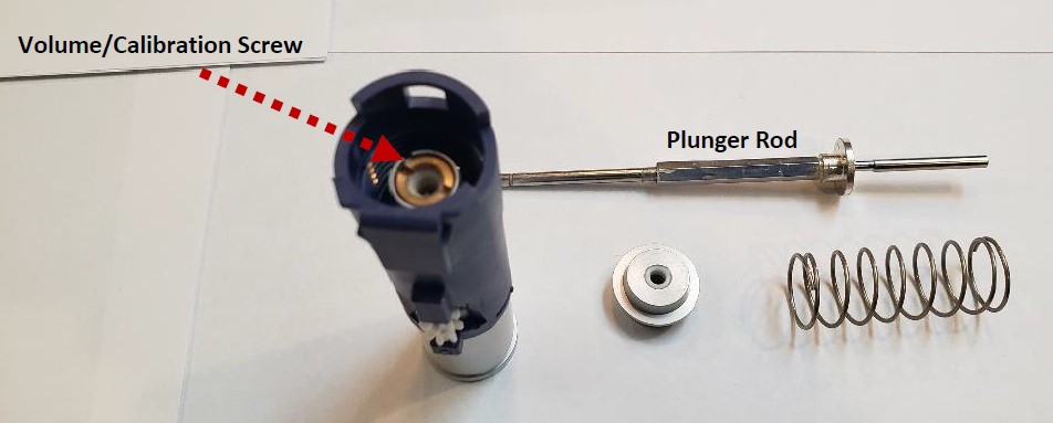
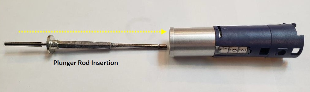
Insert the plunger rod fully into the bottom (silver colored) cylinder assembly until the plunger rod is visible from the top of the volume assembly as shown below.
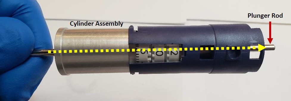
Step 9:
Rotate the plunger rod (the display digits will wind upwards) until the silver/brass colored volume/calibration screw disconnects and can be removed by hand.
NOTE: Remember to write down the digits of the Pipet-Lite counter assembly once the volume/calibration screw is removed. This information will be useful during reassembly.
The picture below shows the volume calibration screw fully removed from the top of the pipette, and plunger rod removed from the bottom of the pipette.
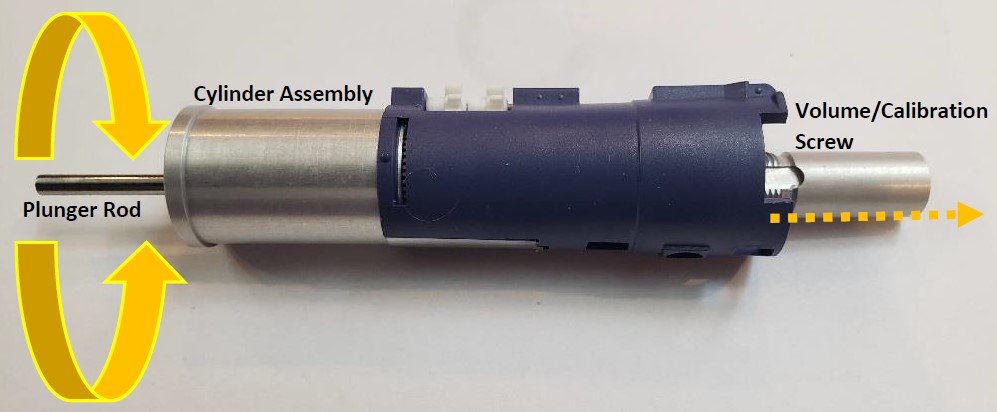
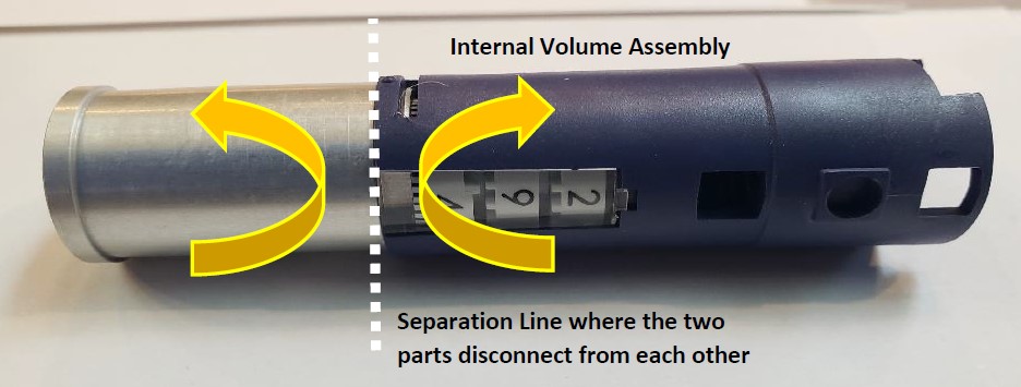
Step 10:
In this step, the silver cylinder assembly will be separated and removed from the volume assembly. Place the cylinder assembly in the left hand and the volume assembly in the right hand. With your thumbs, gently push upward to separate these two parts from each other
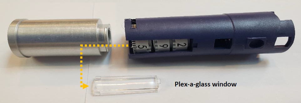
Step 11:
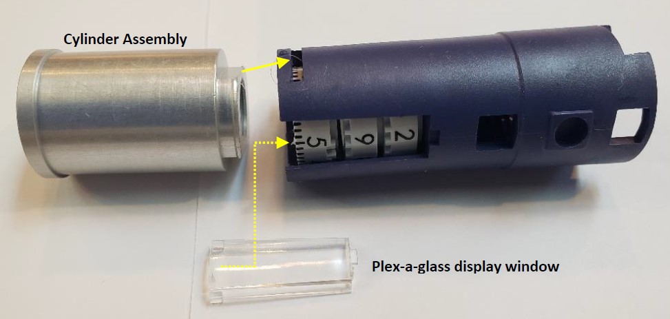
Slide the display plex-a-glass window out.
Step 12:
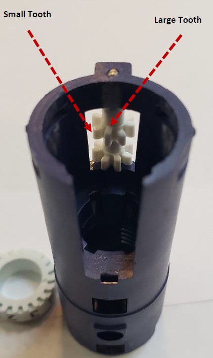
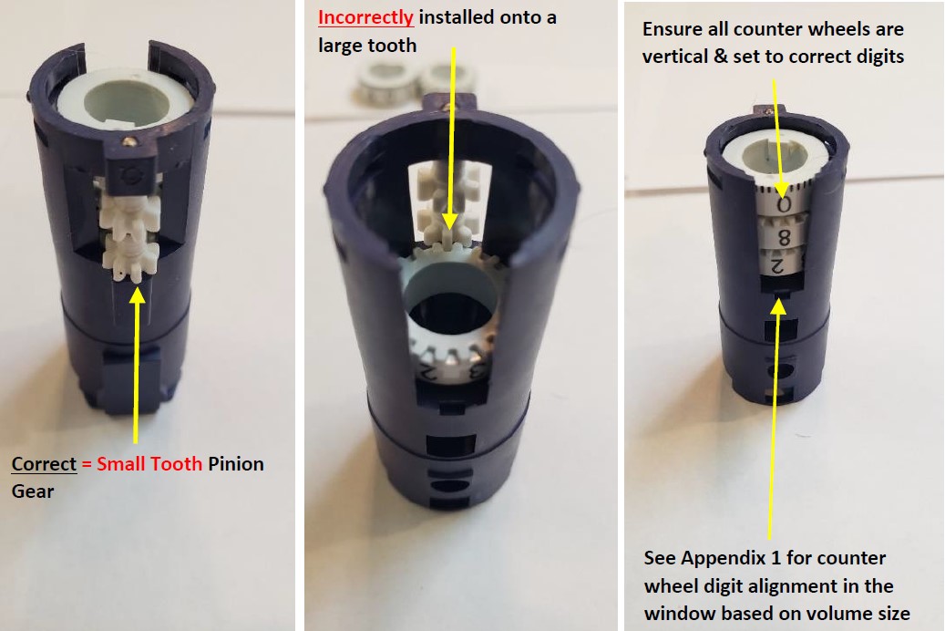
Turn the volume assembly vertically and remove the three (3) white colored digits.
NOTE: Notice the square tab on the bottom digit. This will be important for reassembly of the volume/calibration screw.
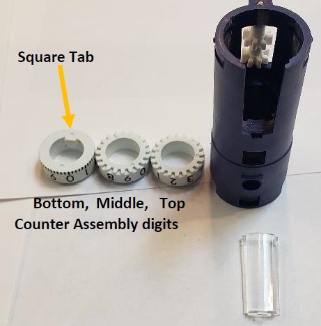
NOTE: During reassembly of the Pipet-Lite counter assembly digits, the top and middle digits will need to be placed on a “small tooth”. DO NOT align them on a “large tooth” as this could lead to the digits not aligning fully in a straight line.
Step 13:
With the counter assembly standing vertically upside down, use a pair of needle nose pliers to insert:
- The top counter wheel first onto the top pinion gear “small tooth”
- insert the middle counter wheel onto the bottom pinion gear “small tooth”
- insert/lay the bottom counter wheel on top of the middle counter wheel
IMPORTANT: The top and middle counter wheels must be inserted into the volume assembly upside down and seat onto a “small pinion gear tooth,” as shown.
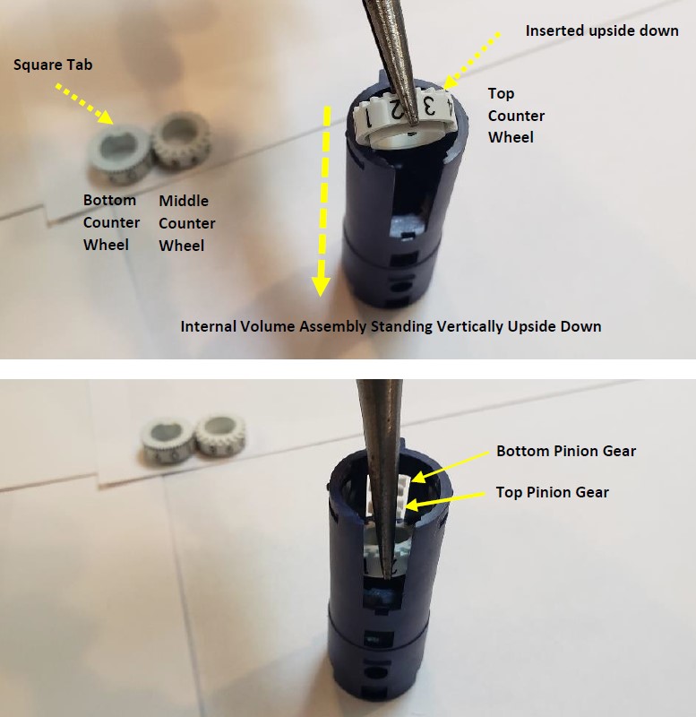
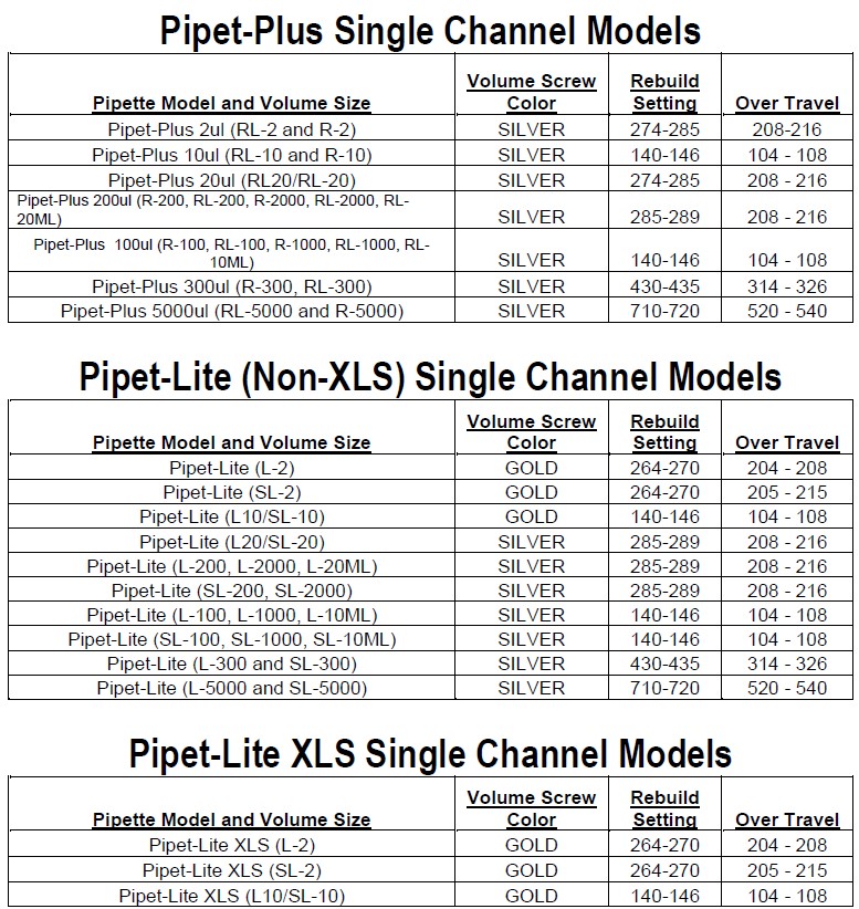
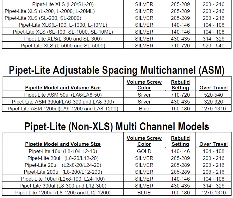
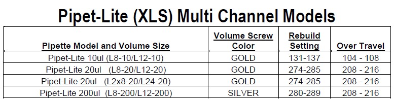
IMPORTANT: when inserting the counter wheels, ensure the correct digits are visible in the window based on
pipette volume size. See Appendix 1
Step 14:
Insert the display window back into the volume assembly. Install and snap the silver cylinder assembly back onto the volume assembly.
Step 15:
Notice the volume/calibration screw and the square tab on the bottom counter wheel. The square tab must align with the slot track on the volume/calibration screw.
Step 16:
In this step, the volume/calibration screw will be re-inserted into the internal volume assembly.
IMPORTANT: Look down inside the volume assembly and align the volume/calibration screw with the square tab on the bottom counter wheel.
Fully insert the volume/calibration screw into the internal volume assembly. Make sure it is inserted fully.
Step 17:
Insert the plunger rod fully into the bottom of the pipette through the silver cylinder assembly.
Once fully inserted, wind the plunger so the volume of the counter wheels wind down to the 10% of nominal.
It’s strongly recommended the internal volume assembly be rotated vertically so the calibration screw is threaded fully into the unit.
Step 18:
Place the bottom stop onto the plunger rod. Insert the blow-out spring down inside the empty pipette body. Install the plunger rod into the internal volume assembly.
Step 19:
Notice the pointed edges of the internal volume assembly. Using the bent nosed pliers, gently spread and enlarge the body opening, while pushing down on the internal volume assembly to align and lock it in the pipette body.
Step 20:
Insert the volume lock bottom into the pipette body and screw it only finger tight. DO NOT over tighten or it will take much more force to lock and unlock the volume lock. Next, snap the volume lock top back onto the pipette.
Place the plunger button back on the pipette.
Screw the shaft assembly back onto the pipette body.
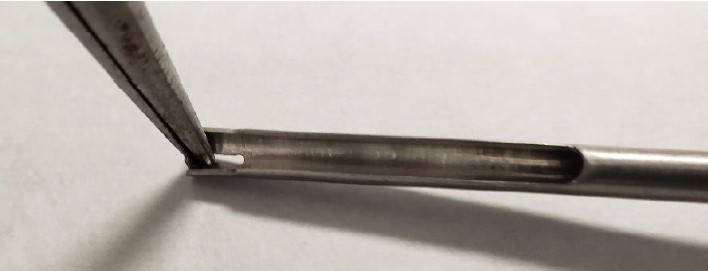
Step 21:
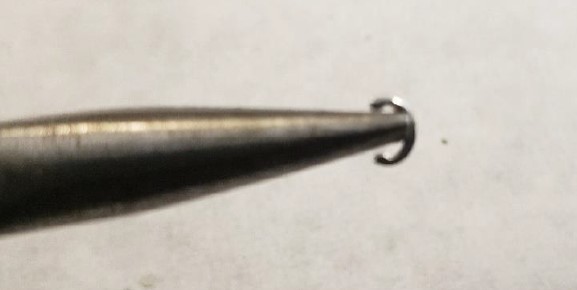
With the needle-nosed pliers, gently grab and hold a c-clip onto the nubs of the pliers as shown in the photo below.
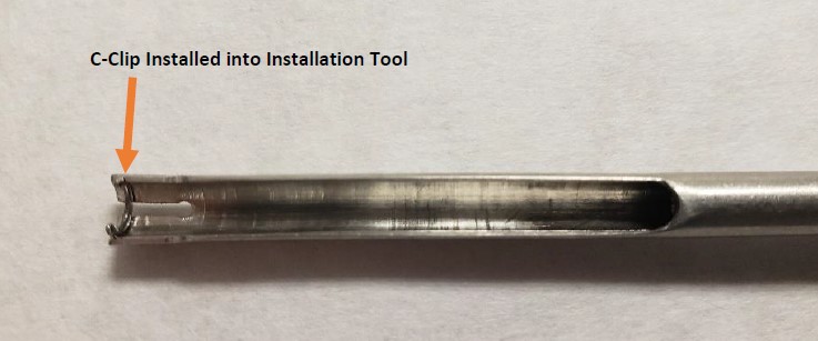
Step 22:
Insert the c-clip into the grooved indentation on the c-clip installation tool.
Step 23:
Notice the c-clip inserted into the grooved indentation on the c-clip installation tool.
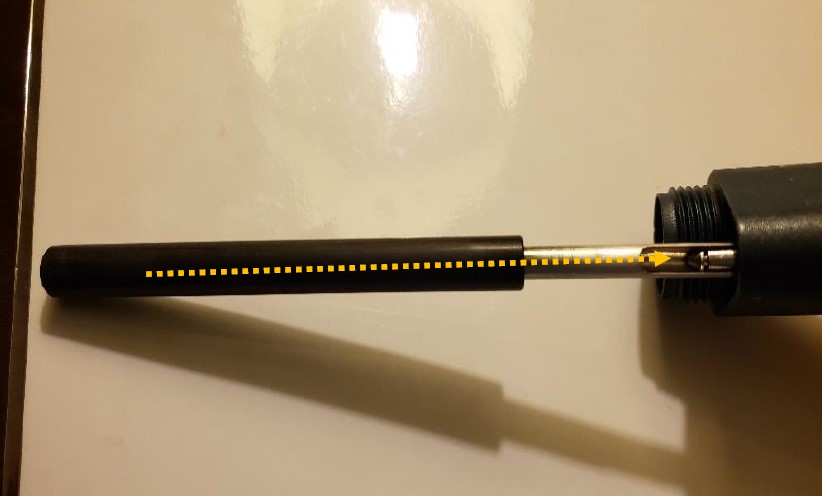
Step 24:
Push and hold the ejector button. Gently slide the installation tool fully into the pointed end of push rod ejector rod assembly until the c-clip catches with the c-clip grooved indentation on the push rod ejector assembly as shown in the
picture on step 8 of Rainin Push Rod Ejector Assembly Replacement.
Step 25:
Push the c-clip tool upward to snap the c-clip back in place until you hear a slight click.
Step 26:
Reattach the tip ejector arm back onto the pipette body.
Step 27:
Recheck your work and correct as needed.
Appendix 1:

Related Posts:
Rainin Push Rod Ejector Assembly Replacement
Rainin Pipet-Lite, XLS, XLS+ Single Channel Pipettes: How to Perform Liquid End Assembly Preventive Maintenance
Seal/O-Ring Vs. Lip Seal for Pipet-Lite, Pipet-Lite XLS, and E4-XLS Models
Pipet-Lite, XLS, XLS+ Calibration Tool, Item # RA CT-2
Rainin Pipette Legend
Disclaimer: Any action you take using the information on this website is strictly at your own risk. The information herein does not constitute professional advice and is general in nature. We make no warranty that this information will meet your requirements, be safe, accurate, or error-free. Pipette Supplies, Inc. is not responsible for any errors or omissions, any results obtained from the use of this information, or any loss or damage arising out of the use of this information. This site is for educational purposes only.
Fair Use: Copyright Disclaimer under section 107 of the Copyright Act of 1976, allows for “fair use” for purposes such as comments, criticism, teaching, scholarship, news reporting, and research.
Fair use is permitted by copyright statute that might otherwise be infringing.