In this post:
Finnpipette Digital Tip Ejector Pusher Mechanism: Based on imprinted volume size on mechanism. Does not include cog wheel or spring. Shop tip ejector pushers.
Tip Ejector Spring – TS 1131820
Tip Ejector Button – TS 10593000
Cog Wheel – TS 10593060
(The Finnpipette Digital Single Channel is the same pipette as the Finnpipette Model 4500 Single Channel)
Background Overview:
- Tip Ejector Button: Cog wheel is hidden from view and on underside of tip ejector button
- Tip Ejector Pusher Mechanism: Ejector spring is hidden from view on underside of ejector pusher mechanism
- White Colored Tip Ejector Sleeve: Ejector sleep fits over the shaft and allows the tips to be ejected.

Finnpipette Model 4500: How to Service and Replace the Tip Ejector Assembly
Step 1:
Gently pull downward on the white colored tip ejector sleeve until it disengages from the tip ejector assembly. Once removed, lay aside for reassembly later.
Step 2:
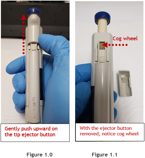
(Figure 1.0) Gently press upward on the tip ejector button with your thumb until it disengages from the lower portion of tip ejector mechanism. Once removed, lay the ejector button aside for reassembly later.
NOTE: (Figure 1.1) Notice the cog wheel is now visible once the ejector button is removed. Please be careful to not lose the cog when the tip ejector pusher mechanism is removed in step 3.
Step 3:
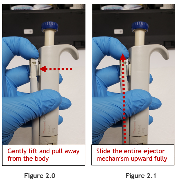
(Figure 2.0) Gently and carefully pull the upper portion of tip ejector pusher mechanism outward and away from the pipette body. Pull just enough so the cog wheel and upper portion of the ejector pusher mechanism no longer contacts the pipette body.
Step 4:
(Figure 2.1) While holding the cog wheel and upper portion of the ejector pusher assembly away from the pipette body, slide the entire ejector pusher mechanism upward to disengage it fully from the body. Once disengaged, lay aside, as shown in figure 3.0.
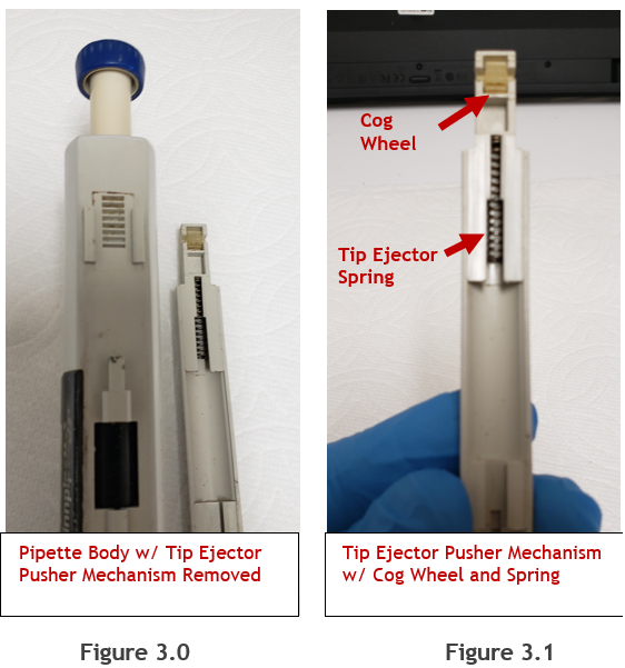
Note: In figures 3.0 and 3.1, notice the cog wheel and tip ejector spring positions/orientation. These parts can be removed for cleaning with 70% IPA and a soft bristled toothbrush. If needed, replacement parts can be found at Pipette Supplies:
- Finnpipette Digital Tip Ejector Pusher Mechanism: PN: Based on imprinted volume size on mechanism and does not include cog wheel or spring. Shop tip ejector pushers.
- Tip Ejector Spring – PN: TS 1131820
- Tip Ejector Button -PN: TS 10593000
- Cog Wheel – PN: TS 10593060
Figure 3.2: Exploited view of the ejector button, cog wheel, tip ejector pusher mechanism, and spring removed from the pipette for easier viewing purposes.

Reassembly Process:
Step 5:
Re-install the tip ejector spring and cog wheel back onto the tip ejector pusher mechanism.
Step 6:
Align the tip ejector mechanism slits with the slots on the pipette handle, as shown in figure 4.0. Push the tip ejector pusher mechanism downward until it is fully seated back onto the pipette (Figure 4.1).

Step 7:
(Figure 4.2) Re-install the tip ejector button onto the tip ejector pusher mechanism by pushing downward.

Step 8:
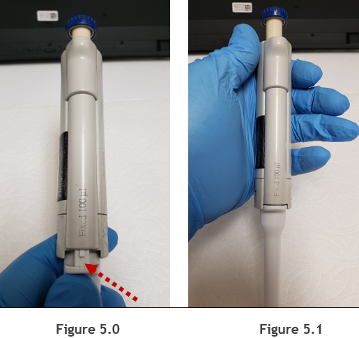
(Figure 5.0) Re-install the white colored tip ejector back onto the pipette by aligning it with the tip ejector pusher mechanism. Once aligned, push upward until it is secure.
Step 9:
(Figure 5.1) Check reassembly by loading and ejecting tips multiple times. Re-check your work as needed.
Disclaimer: Any action you take using the information on this website is strictly at your own risk. The information herein does not constitute professional advice and is general in nature. We make no warranty that this information will meet your requirements, be safe, accurate, or error-free. Pipette Supplies, Inc. is not responsible for any errors or omissions, any results obtained from the use of this information, or any loss or damage arising out of the use of this information. This site is for educational purposes only.
Fair Use: Copyright Disclaimer under section 107 of the Copyright Act of 1976, allows for “fair use” for purposes such as comments, criticism, teaching, scholarship, news reporting, and research.
Fair use is permitted by copyright statute that might otherwise be infringing.